Let there be sound!
- published
Haha, it works! I took some time today to fabricate a quick circuit that can drive a speaker or headphone without blowing anything up or distort the signal. Some breadboarding and soldering later, I hooked up my head phones to hear for the first the the actual sound of the VCO.
Volume control
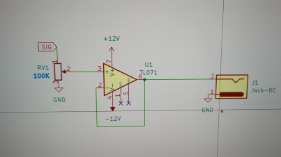
This is a simple, but effective circuit that allows you to take the output signal of a module which has some 10V peak to peak amplitude and turn it down to the mV range so it can be used for headphones / line equipment. There a pot that controls the voltage at the + input of the opamp. The opamp is configured as a buffer which means it will try to get the same voltage between output and ground as there is between + and - on the opamp. It does this by driving current into the headphone. Effectively this circuit decouples the headphones from the VCO so that the VCO does not need to supply the driving current which would degrade the signal.
Generally, I’m very happy with the result, except it sounds rather raw. I think it’s kind of cool, just not sure if its supposed to sound like this. I imagined the sinewave to sound purer, cleaner? Maybe there are some overtones that are not supposed to be there. I remember having used a 22pF cap somewhere instead of a 10pF. Perhaps, that’s the culprit? Time will tell …
Square wave with PWM at the end
Sine wave
Triangle wave
Sawtooth wave
Jumper wire storage
This is how I store my jumper wires now. I stuck the soft part of a bunch of velcro onto a board and used the hard part to stick the wires down.
