Posts
Upon review of the diagrams, a bug in the was found in the toolkit currently under development.
Work done
A set of two tools have been developed:
BNF2AST2JSON
As the name suggests, this tool take the BNF representation of the IEEE1800-2023 standard, converts it to an AST and then outputs this AST in JSON format, so it may be stored on a filesystem.
The tools works as follows:
-
The BNF structure has been codified in PEG syntax and stores in
bnf.pest. This file describes the structure of the BNF format as used in the IEEE1800-2023. This standard does not fully adhere to the BNF spec, so it is a custom description.
Work done
Over the last days of 2025, some effort has been made to copy the grammar syntax from appendix A to a BNF file and a Zim document structure.
The BNF file will be used by a tool to create a graph of the language.
The Zim document is used to make notes regarding the function of each element.
Haha, it works! I took some time today to fabricate a quick circuit that can drive a speaker or headphone without blowing anything up or distort the signal. Some breadboarding and soldering later, I hooked up my head phones to hear for the first the the actual sound of the VCO.
Volume control
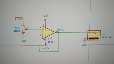
This is a simple, but effective circuit that allows you to take the output signal of a module which has some 10V peak to peak amplitude and turn it down to the mV range so it can be used for headphones / line equipment. There a pot that controls the voltage at the + input of the opamp. The opamp is configured as a buffer which means it will try to get the same voltage between output and ground as there is between + and - on the opamp. It does this by driving current into the headphone. Effectively this circuit decouples the headphones from the VCO so that the VCO does not need to supply the driving current which would degrade the signal.
The past two weeks I spent off and on assembling the PCB in small increments. It was fun to so some soldering after so long. Also, the jig, the solder holder, the extraction unit and the head mounted magnifying glasses are a huge help. Working on electronics with good equipment is such must, as they solve the problems of: a wobbly PCB, not being able to see the joints well, etc. These things don’t really stand out when you’re starting out, but get really old when you well, get older :)
The circuitboard layout design of the VCO has been completed. My tool of choice to design circuitboard is KiCAD. I have evaluated Altium Designer, but as far as I can see, for simple designs KiCAD fits the bill. The only thing KiCAD is missing, but Altium has, is a way to link part to a manufacturer and supplier so one can quickly select parts, see stock,find alternatives etc.
However, I digress. The design is available here.
The breadboarding is pretty much done. The beasty works on the scope. I have not been able to actually get some audio out of it yet, because I have not built the module that will adapt the signal to something that can be used by an amp or headphones. Also, I do not have an amp yet, nor monitor speaker yet, nor any idea of what to get :)
Calibration turns out to be a bit of a SoB. It is hard to get a good wave-form that will persist. When I tap one of the pots, ever so slightly, the shape distorts. This was giving me a head-ache, and I’m blaming the breadboard. I have made a PCB design. (available here). It’s just for the VCO at this moment. When it is ordered, I’ll build it and I hope the problem magically goes away.
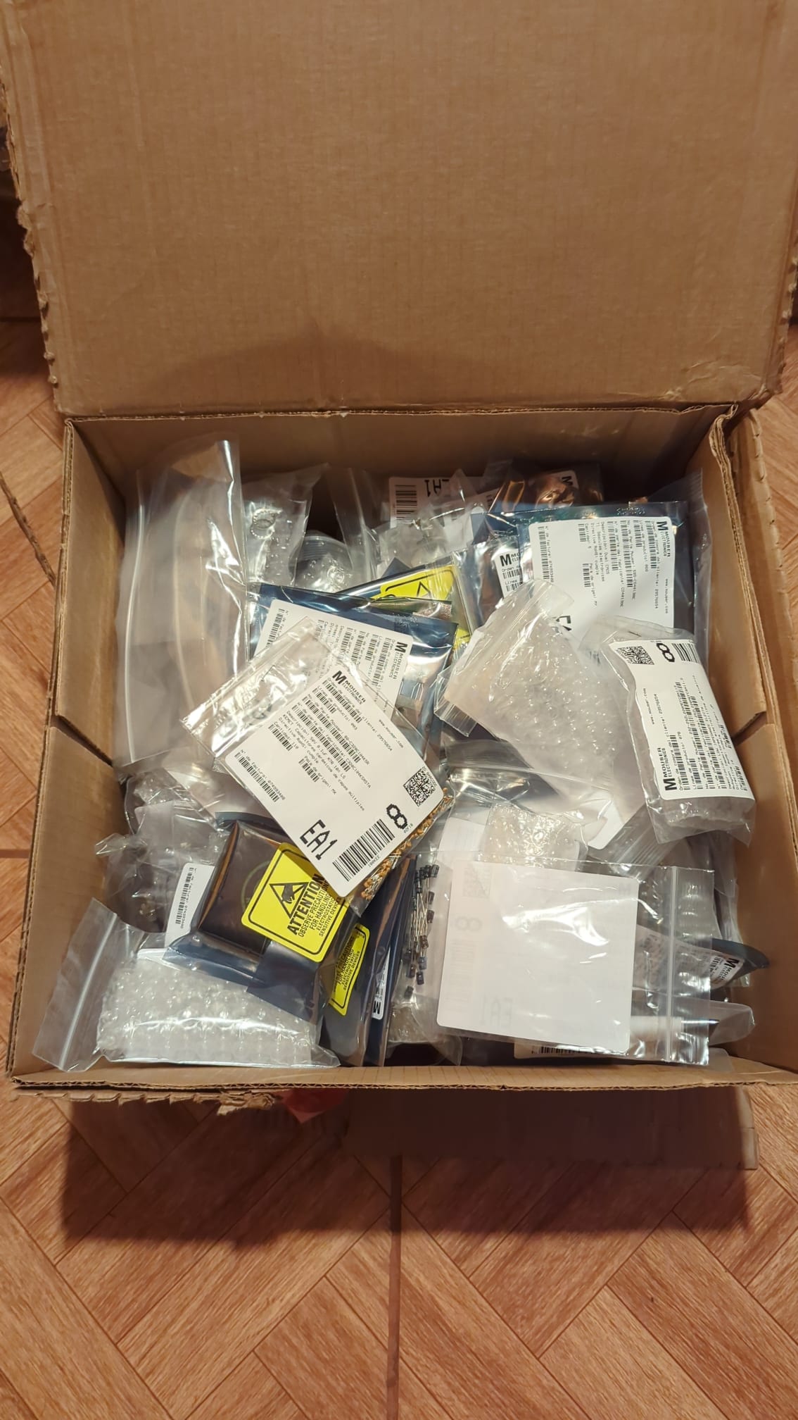
The parts for the mfos-vco project and other synths have arrived! Now to find a place to store it all.
I have equipped the laser with a honey comb bed. The previous bed was a rudamentary pin bed made of aluminium profiles and bolts. The distances between the pins was too large, causing the parts to flip and get hit by the laser head. This in turn would move the board, causing mis-alignment and ruining the job.
The bed consists of 2 60x60 panels. I had to do some custom hacking as the honeycomb comes in a square frame. So, I had to remove one side of the frame. Fortunately, the frame is rivetted, which can be drilled out. I repurposed some of the aluminium profiles to act as a support under the honey-comb where the mesh meets, so it won’t get all wobbly and maintains solidness.
For the past year I’ve been working on a laser cutter.
Though it’s not completely finished, it is operational.
Checkout the project page for specs, vids and pics!
Building the MFOS VCO and other synth modules. I will be starting with the VCO. See project page