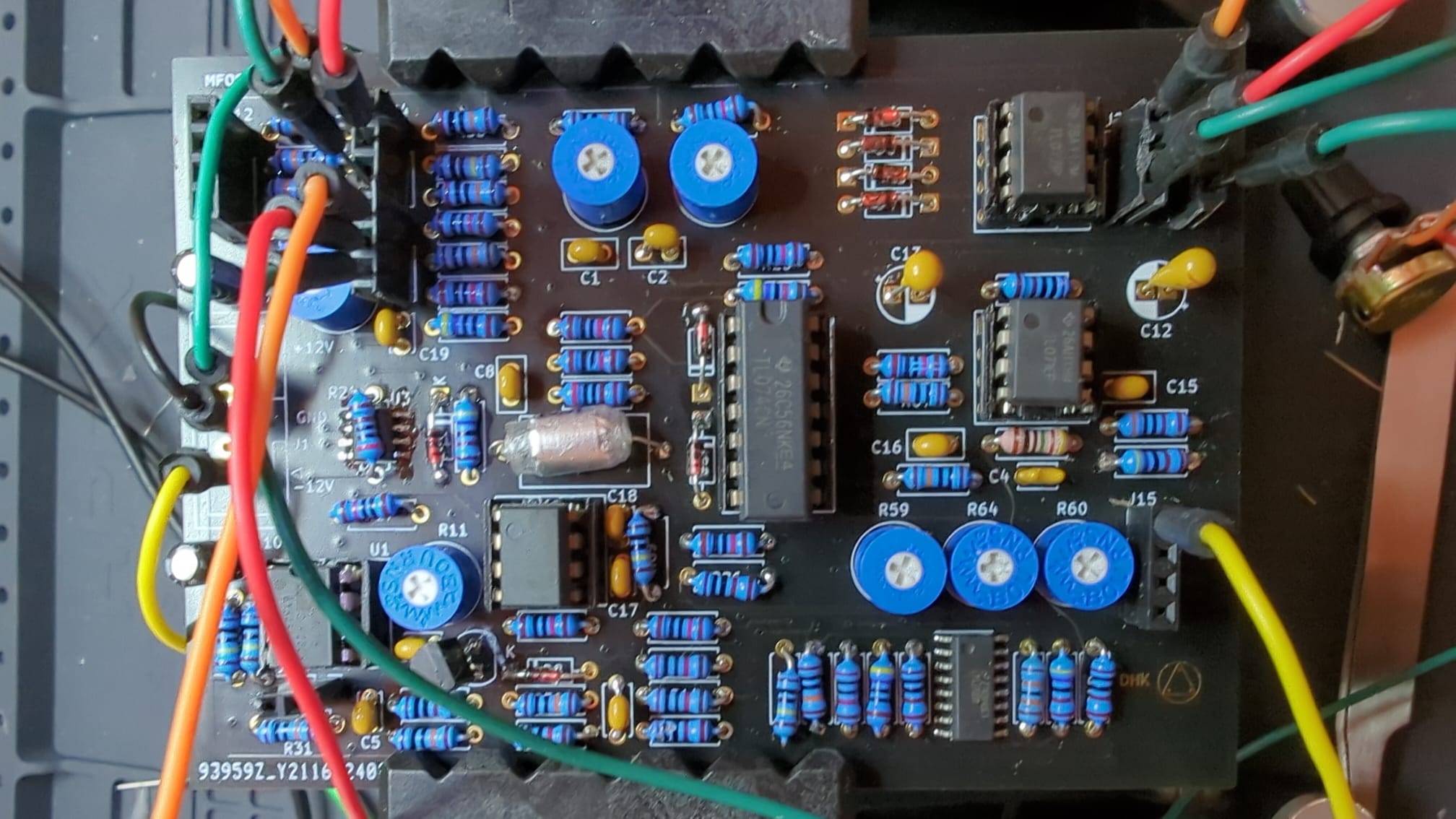
PCB assembly VCO prototype complete
- published
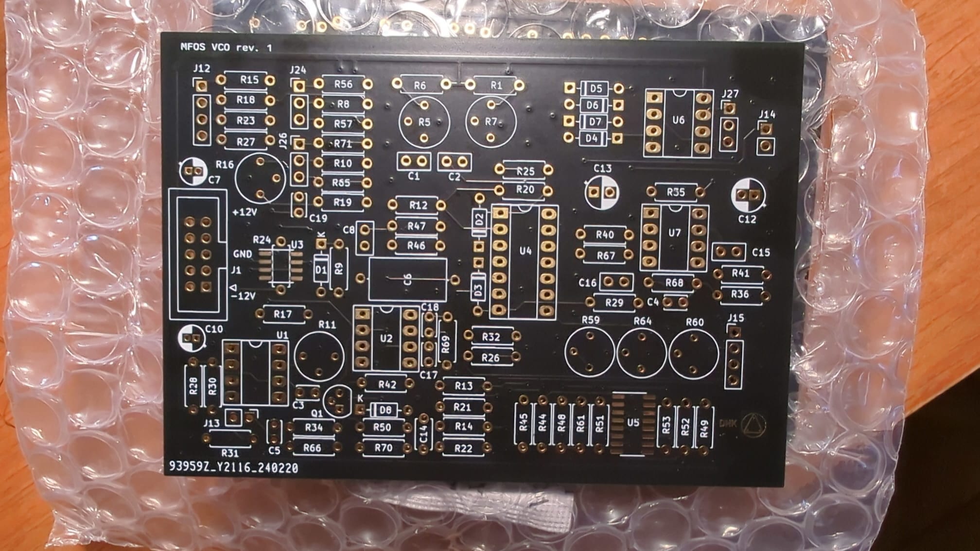
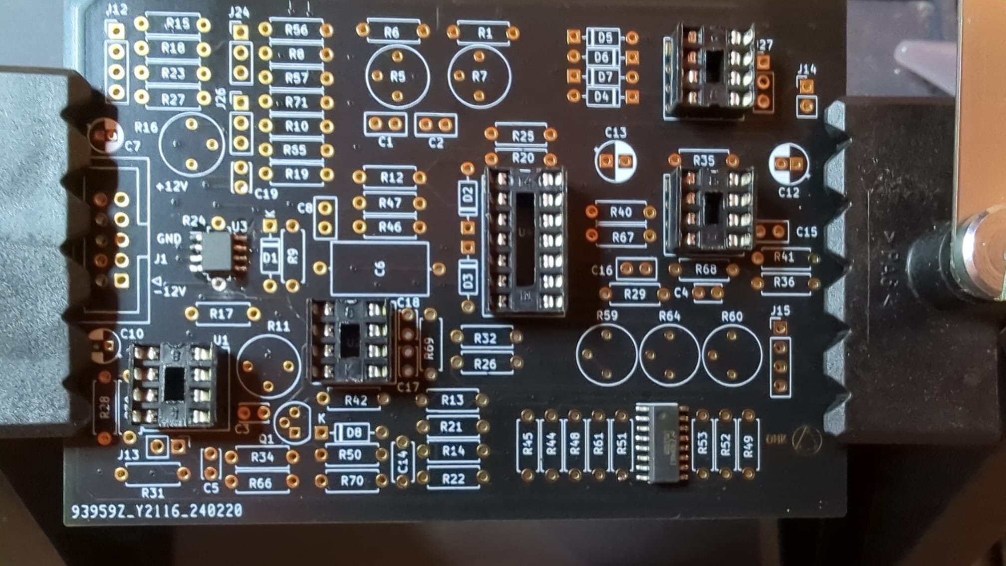
The past two weeks I spent off and on assembling the PCB in small increments. It was fun to so some soldering after so long. Also, the jig, the solder holder, the extraction unit and the head mounted magnifying glasses are a huge help. Working on electronics with good equipment is such must, as they solve the problems of: a wobbly PCB, not being able to see the joints well, etc. These things don’t really stand out when you’re starting out, but get really old when you well, get older :)
Anyway, the board is a success with one real error and some minor issues in the design and while assembling. The error consists of the fact that the PN4891’s packages is of type Drain-Source-Gate (DSG). This means that pin 1 is drain, 2 is source and 3 is gate. I missed this detail when selecting a model in Kicad. I just picked a JFET model, without considering the pinout. The usual is DGS, so the source and drain were swapped.
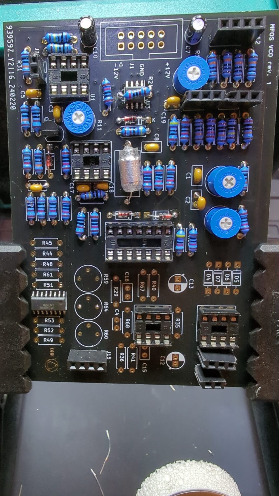
This resulted in the VCO not showing any output at all. So, I fired up the scope and placed a probe at points with an expected output. When I saw a flat line, I knew the problem had to be higher up the hierarchy. At one point I touched all the parts and the JFET was running a little too warm, which made me suspect the problem was with the component. Lo and behold, after replacing the part the VCO showed some improvement.
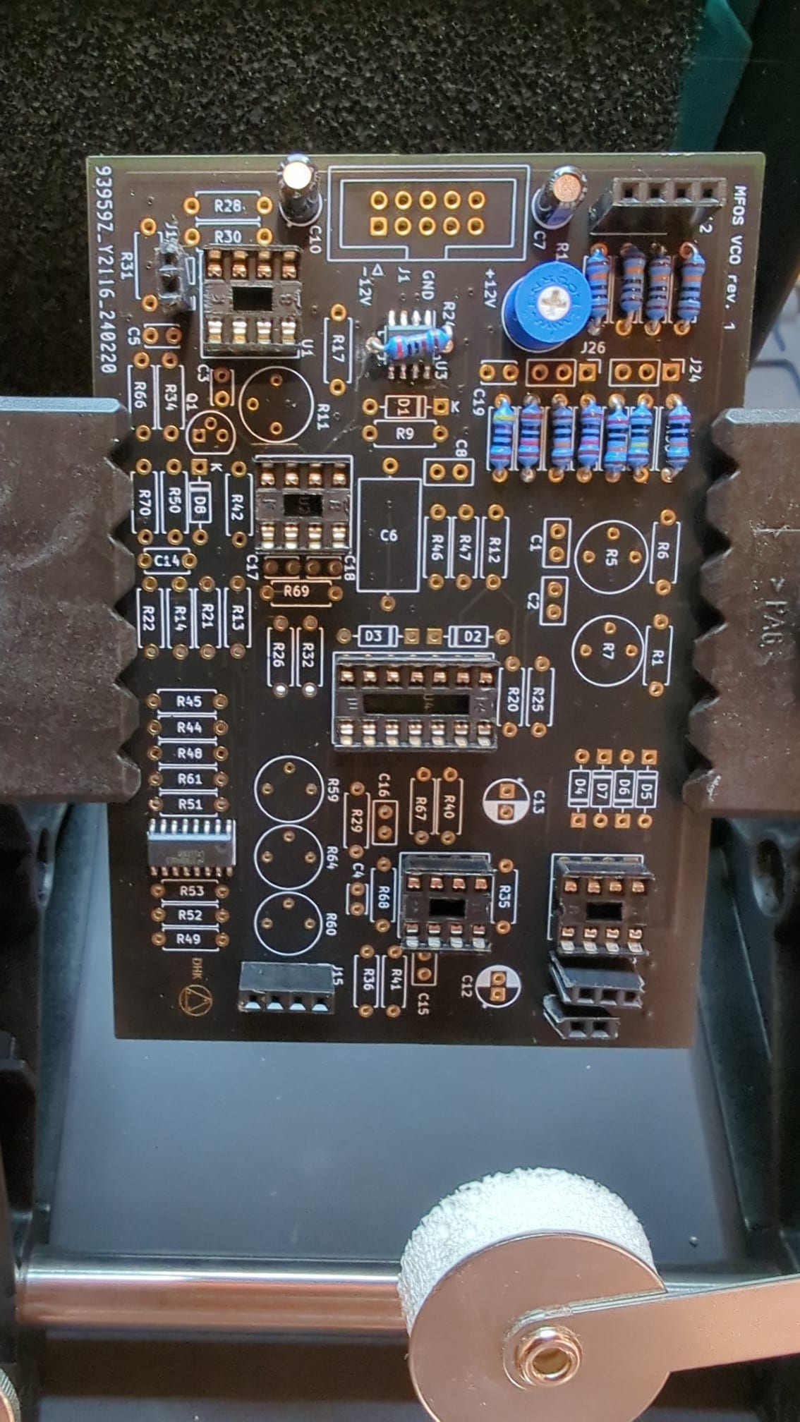
I had to twist and turn some of the trimpots to get the right shape for SIN and to get the signals biased correctly, but apart from SQR everything looked fine.
I mistakenly used a 47K ohm resistor instead of a 4.7K resistor for R36 resulting in the amplitude of the squarewave to be reduced by apparently a factor 10. Desoldered the part, replaced with the correct value and also SQR behaves a-ok.
I have fixed the error and made some space for proper molex KK connectors and some cosmetic changes in revision 2 of the board which is now in production at dirtypcbs.
The VCO can produce waves with a frequency of ~2Hz. - ~60 kHz. The waveshape is rubbish at these high frequencies, but human’s won’t be able to hear them anyway. The VCO can get even lower than 1.9322Hz, but the frequency counter is having trouble measuring the frequency at such low frequencies.
In the triangle waveform you can see a bit of a pronounced glitch at the bottom of each period. I have use a 22pF cap instead of a 10pF, since I didn’t have a 10pF. Not sure if this is audible, but I have since ordered 10pF caps and will replace nonetheless. The other triangle waveform is measured at 60kHz and looks a bit distorted.
The irony is that though this is a device intended to produce sound, I have not listened to it. I have verified operation on the scope only. One of these days I’ll build a small device with a volume knob and a headphone connector to have a listen.
There is still some tuning and testing to be done, but not bad overall.